Saturday, January 14, 2012

Breadboard Arduino

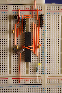
Received a couple of nice big bread boards for Christmas and decided that one of them needed an arduino to use with it. After some thought I decided that the best option was to build the required parts of an Arduino circuit direct on the breadboard. Also the cheapest at only £4 for the required parts.

The required sections of the circuit for general Arduino development are:
ATMega micro-controller, in this case an ATMega328 with 100nF capacitor across ground and VCC near chip
Oscillator - 16MHz crystal and 2x 22pF capacitors
Reset - push to make button and 10KOhm resistor
Serial programming - 6 pin header, reset decoupling capacitor 100nF

Optional sections are:
Pin13 LED - LED and suitable resistor
ARef smoothing - 100nF capacitor
ISP - 6Pin header to allow connection to an In System Programmer

If you don't have the use of an in system programmer for the ATMega devices then the ATMega328 needs to be purchased with the Arduino bootloader already flashed to it. There is little difference in cost. I used the Duemilanove bootloader.

Also required is FTDI USB to TTL serial adaptor. I prefer the Sparkfun "FTDI Basic" board because breaks out DTR rather than RTS as in many converters. This means that the Arduino IDE can reset the Arduino itself when uploading programs. A USB to Serial converter which provides RTS can be used but you have to manually reset the Arduino circuit during the programming cycle.

The circuit I used is provided here in picture on the right. Also I as was using Fritzing an image of the a bread board layout is provide.


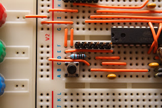
The photos below shows a close up of the serial programing connection and on the right some of the wiring is removed to show hidden links.
Tuesday, December 20, 2011

Diner Light


The prototype Diner Light is up for Christmas. Using the touch sensor from the previous post to give independent control of 4 LED spot lights to individually light the four seats at our family dining table.

The Christmas holidays should thoroughly test the prototype. Then a final version can be manufactured in the new year with any modifications. Already on the list is a master touch sensor for all on and all off control. Oh and a pretty case to make it an acceptable addition to the lounge. The PCB design is already almost complete in Fritzing.

Details on the touch sensor design used is given on my website. It is very simple using just a diode and 2 resistors to provide capacitive touch sensing. The only change required for use in the Diner Light was to change to using a port interrupt on the Arduino so that 4 channels of interrupt could be implemented on a Atmega328 Arduino.

The LED lamps are driven via a simple transistor current source, thus making the supply voltage non-critical. Further details of the design will be published in the new year with a documentation of the build of the final version. So for now an excerpt from the circuit is shown below. It shows all the main circuit component structures, a touch sensor is on the left and a constant current LED drive is on the right of the Pro Mini.

Friday, December 9, 2011

Touch sensor on Arduino

With a task to build a table lamp under way I decided that I needed a touch sensor. Well four of them really, to control the individual place lighting. Low and behold the next day hackaday has a post on a touch sensor using the capsense library. So I hook up the circuit used with the library and write a bit of code to control and measure the sensor. But I wasn't convince by how it behaved. The circuit used tries to measures the charge rate of the capacitance provided by human touch. However I found that leakage currents in my cobbled together circuit stopped the capacitance charging even to half the supply voltage driven out an Arduino IO pin. The set up still sensed a definite and repeatable change upon touching the sensor plate but this was due to the fact that I was applying ~10V of mains pick-up to the circuit. Whilst I expect there is a way to build this circuit with less leakage and susceptibility to electrical pick up from the human user I wanted something less picky for my solution. Mainly because I only want to build it once. So back to the web.


Further research showed that most methods measure discharge of the capacitance or voltage drop of a charge capacitor switch to the sense plate. The second method gets into more low level micro controller coding than I want to. So the discharge method looked best bet.

I rigged up the circuit shown above which uses an output pin on the Arduino to charge the capacitance of the circuit through a diode, which avoids having to switch the pin to high impedance. This drive pin is set as a PWM output which provides a 490Hz drive to the circuit. The sense point of the circuit is connected to an interrupt pin on the Arduino has a resistor, ~3Mohm, connected to ground to discharge the circuit's capacitance once the supply pin is switched off. The sense plate for the test set up was a piece of painted aluminium alloy sheet with a screw holding the connection wire to it. The sense plate is connected to the circuit's sense point via a 12KOhm resistor to provide protection from ESD. It should be noted that diodes have a parasitic capacitance which can be anything from .5pF to 200nF or so depending on the type. If a diode with very low capacitance is used then an extra capacitor of a few pF connected between sense point and ground may be required. The diode I used is a 1n4148 which is a small high frequency signal diode which I would expect to have a 5 to 15pF capacitance. If a diode with large capacitance is used then the circuit changes little with the addition of the human touch capacitance.

The Arduino needs to be set up to have a change interrupt on the input sensing pin. I simply used the Arduino standard pin interrupt commands for test. The final 4 channel touch sensor for the lamp will require a port interrupt to be configured as a pro mini will be used. For more info, a code example and the circuit diagram go to Arduino Touch .

Friday, July 2, 2010

In flight current meter / logger for RC aircraft


In flight current and temperature logger for radio controlled models. Allows electric power setup to be tuned using inflight measurements rather than ground based testing. The core is an Arduino nano that I had lying around. The current sensor is a zero to 30A ACS715 hall effect device on a breakout board ready assembled. The temperature sensor is a TMP102 ready assemble on a breakout board, it uses an I2C interface. These devices are just wired to the Arduino and it is ready to go.

Once complete motor current and battery temperature can be monitored in flight.

For more info go to http://myweb.tiscali.co.uk/assocofbodgeartists/Articles/InFlightMeter/InFlightMeter.html.

Monday, June 14, 2010

Low cost modifications to Parkzone micro Sukhoi for better aerobatics

The Parkzone micro Sukhoi is a lovely aeroplane. With full 4 channel control it is capable of all classic aerobatics. However out of the box it lacks the thrust and control response for good aerobatic performance. It has poor vertical performance looses too much speed in loop and Immelmans to make it cleanly over the top. So a few mods are in order.

Mod 1: Get the CoG further back

To achieve this without the addition of weight the main RX board with its elevator and rudder servos needs to be moved back from its original position behind the motor. So cut the decals to remove the top cover. Remove the push rods for rudder and elevator. Unplug motor and aileron servo. Carefully remove the RX board by cutting away the foam. Carefully remove most of the remains of foam and glue from the RX board, just enough to ensure the board sits flat and no excess glue sticks out the sides. Using double sided tape mount the RX board to the rear section of the wing as shown in the picture above. Make a hole in the rear of the battery bay for the battery plug to pass through. Extend the motor wires and plug motor and aileron servo back into the RX board. Cut the push rods shorter as required. Remove Z bent wire from discarded ends and fit to end of short push rods with very small bore heat shrink. Offer up push rods adjust position of Z bent wires for best fit and wick a little thin cyano under the heat shrink. Refit push rods, use second hole out from hinge on surface control horn and 30 to 50% exponential on rudder and elevator for good aerobatic response. Test controls for full and free movement, bend wire loop and rear end of push rods as required ensuring controls are central when TX sticks are central. Re-attach cover with some clear fablon patches.

Mod 2: Change the Prop

The original prop just doesn't seem right, it's either under loading the motor or overloading it I can't quite work out which. However a 5 inch diameter 4.5 inch pitch GWS slow fly style prop seems ideal, cheap and light. To mount the prop I drilled down the middle of a nylon screw so that it would self tap onto the gearbox shaft thus providing a prop shaft to mount the prop. However gluing a piece of plastic tube into the hub which could then be screwed onto the shaft would be a little lighter.

With these mods implemented flight was superb with smooth and easy loops and rolls.

Tuesday, April 27, 2010

Making tin fuel tanks for model aircraft


A tutorial on making tin plate fuel tanks for model aircraft has been added to the InfraCortex website.

http://myweb.tiscali.co.uk/assocofbodgeartists/Articles/tintank/tintank.html

Monday, March 22, 2010

Swing between two posts


As with most families in the UK we have a relatively small garden. But of course we want to provide fun toys in the garden for the kids to play on.

Initially I am installing a set of removable posts so the garden can be configured for different purposes. One of my first problems was how to rig a swing between 2 posts ~4m apart. The solution is a trianglated rope swing.

The top rope forms two triangles providing support points at approximately the width of the seat, thus the seat can be made stable with respect to side to side motion. Snap shackles are used to clip the swing to eye bolts in the posts. This makes the swing easily removed. One extra snap shackle is used to join the ends of the top rope in the middle. The swing seat is supported conventionally below the top rope triangles. The posts need support bases that extend 2feet or more below ground as they have to act as canteliver supports.